ZXPS Assembly Instructions
Version 0.9 October 24, 2024 Download PDF
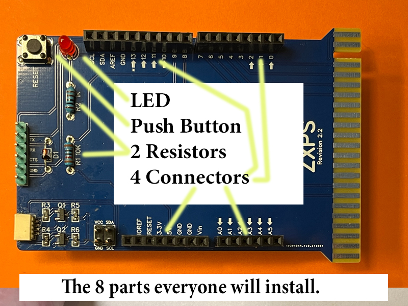
STEP 1: Bend the leads, insert and solder R1 10K 1/8w axial lead resistor
|
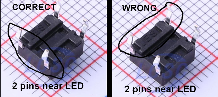
STEP 3: Insert and solder SW1 Push Button Switch.
STEP 4: Insert and solder the LED. The shorter lead, which is the flat side fo the LED base is the cathode. Insert this in the PCB hole marked minus - This completes the installation of all the components most people will need to use the ZXPS. |
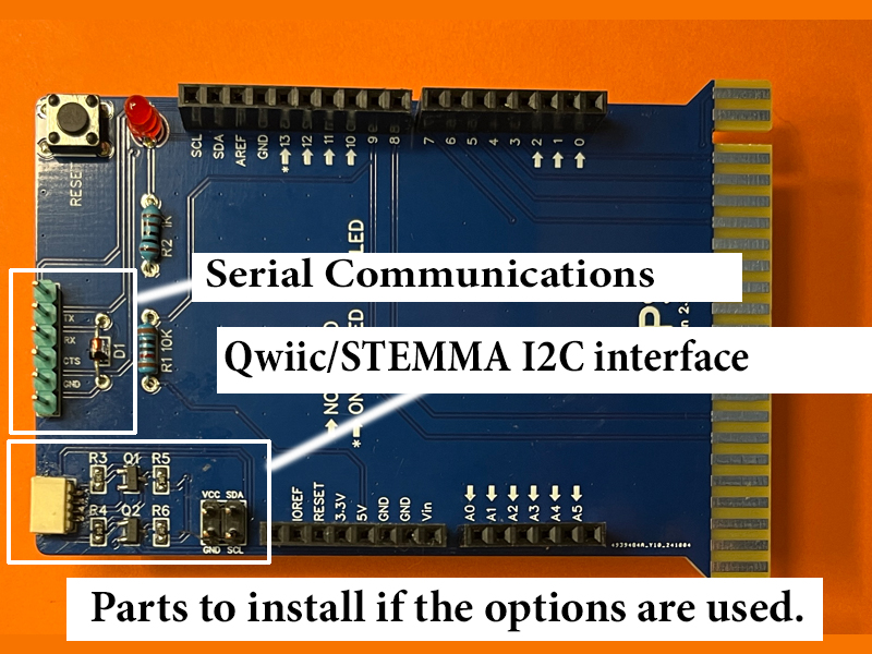 |
Components for Arduino Serial Communication There are holes on the PCB for J1 which some people might want to use for certain serial connection applications. A 6-pin simple header is supplied as one options if you choose to use these signals. The ZXPS ships with a 6 pin header for use as J1. |
|
If you are going to interface to a 3.3 or lower voltage I2C sensor you may want to use the optional Qwiic/STEMMA circuit on the ZXPS. IMPORTANT NOTE: The ZXPS Qwiic/STEMMA is implemented with Arduino pins A4 and A5, which are not the standard Arduino I2C pins and requires the use of an I2C software library. Depending upon your Arduino programming skills, you may find this easy or difficult. Additional ZXPS support documention for this is being developed. |
|
The ZXPS Qwicc/STEMMA interface uses 8 SMD components, but to install it requires good eyesight and surface mount device soldering skills and tools. I personally have have assembled these components at times solely with a soldering iron, at at other times with a hot air gun. Both ways, I found it challenging. Assembly recommendations for this Optional Qwiic/STEMMA I2C Interface, probably including a video, will be released soon. |

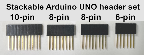 STEP 5: Insert and Solder your stackable header connectors. CAUTIONS: Generally it is best to solder a single pin on a connector first and then make sure the connector is perpendicular to the PCB. Then solder the remaining pins on the connector. Also, be careful to solder the pins only near the circuit board leaving clean pins that easily insert into the Arduino header sockets.